Description
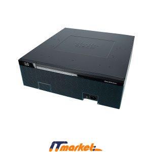
CISCO3925E/K9 Overview
The Cisco 3925E router is designed for large branch offices, which delivers modular Services Performance Engine (SPE) 200.
Quick Specs
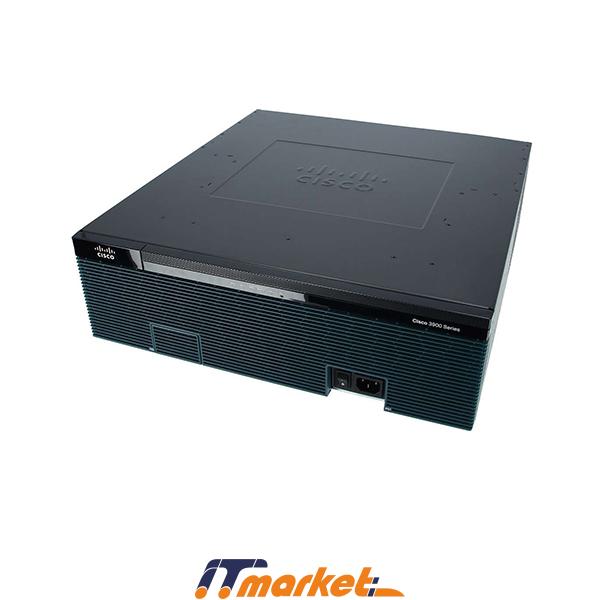
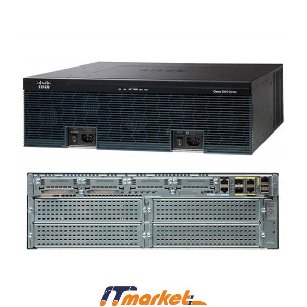
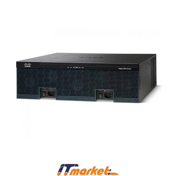
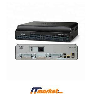
Figure 1 shows the appearance of the CISCO3925E/K9.
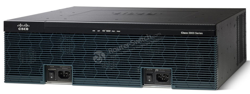
Table 1 shows the Quick Specs of the CISCO3925E/K9.
| Product Code | CISCO3925E/K9 |
| Services Performance Engine module | w/SPE 200 |
| Rack Units | 3U |
| Interfaces | 4 integrated 10/100/1000 Ethernet ports with 2 SFP ports |
| Expansion Slot(s) | 2 service module slots 3 onboard digital signal processor (DSP) slots 3 Enhanced High-Speed WAN Interface Card (EHWIC) slots |
| RAM | 1 GB (installed) / 2 GB (max) |
| Flash Memory | 256 MB (installed) / 8 GB (max) |
| Dimensions | 47.6 cm x 43.8 cm x 13.3 cm |
| Package Weight | 23.52 Kg |
Product Details
Figure 2 shows the front panel of the Cisco 3925E/K9 router.
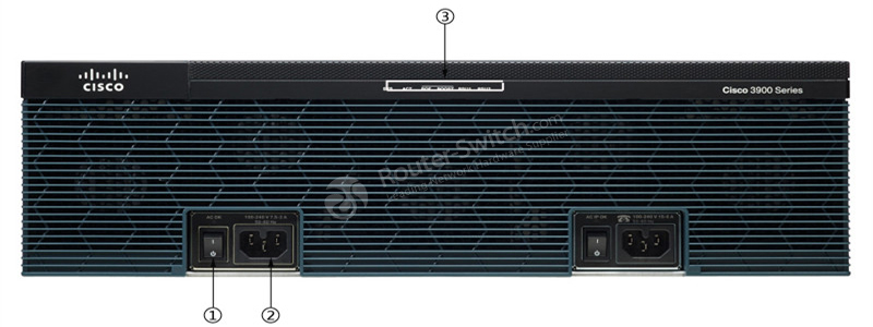
Note:
| ① | ② | ③ |
| On/Off switch | Power connector | LEDs area |
Table 2 shows the LEDs area description.
| LED | Description | |
| SYS status LED | Solid green | Solid green indicates normal operation. |
| Blinking green | System is booting or is in ROM monitor mode. | |
| Amber | System error. | |
| Off | Power is off or system board is faulty. | |
| ACT status LED | Solid or blinking green | Solid or blinking indicates packet activity between the forwarding and routing engine and any I/O port. |
| Off | No packet transfers are occurring. | |
| POE | Green | IP phone power is on. |
| Amber | IP phone power is not on. | |
| PS1 / PS2 | Green | System is running. |
| Amber | System is not running. | |
![]() The back panel of CISCO3925E/K9 is similar with the CISCO3945E/K9 except that CISCO3925E has only 2 Services Module Slots.
The back panel of CISCO3925E/K9 is similar with the CISCO3945E/K9 except that CISCO3925E has only 2 Services Module Slots.
Figure 3 shows the back panel of the Cisco router 3945E/K9 with LEDs, for reference only.

Note:
| ① | Compact flash 0 and 1 (0, right) | ⑤ | S (Speed) |
| ② | PVDM3 0,1, and 2 (0, far right) | ⑥ | L (Link) |
| ③ | EN (Enable USB console) | ⑦ | SFP S |
| ④ | EN (Enable RJ-45 console) | ⑧ | SFP EN |
Table 3 shows the description of these LEDs on the back panel.
| LED | Color | Description | Location |
| CompactFlash 1 | Green | Flash memory is busy. | Back Panel |
| Amber | Initialized with error. | ||
| Blinking Green then turns off | CompactFlash is ready for removal. | ||
| CompactFlash 0 | Green | Flash memory is busy. | Back Panel |
| Amber | Initialized with error. | ||
| Blinking Green then turns off | CompactFlash is ready for removal. | ||
| S (Speed) | 1 blink + pause | GE port operating at 10 Mb/s. | Back Panel |
| 2 blink + pause | GE port operating at 100 Mb/s. | ||
| 3 blink + pause | GE port operating at 1000 Mb/s. | ||
| L (Link) | Green | GE link is established. | Back Panel |
| Off | No GE link is established. | ||
| EN (RJ-45 console port) | Green | The RJ-45 console port is active. | Back Panel |
| EN (USB serial console port) | Green | The USB console port is active. | Back Panel |
| PVDM3 0,1, and 2 | Green | PVDM is initialized. | Back Panel |
| Amber | PVDM is detected but not initialized. | ||
| Off | No PVDM installed. | ||
| SFP S | Blinking green | Blinking frequency indicates port speed. | Back Panel |
| SFP EN | Off | Not present. | Back Panel |
| Green | Present and enabled. | ||
| Amber | Present with failure. |

